Today’s post delves into Power over Ethernet technologies
 Managing power can be important – as a certain starship captain was fond of yelling into the intercom, “Give me full power in 5 minutes, or we’re all dead!” With this in mind, today’s post begins a two-part examination of Power over Ethernet technology. Part I will cover the origins of PoE and the original PoE standard. Part II will cover PoE+, and the future of PoE.
How PoE Came to Be
One of the earliest concerns about VoIP phones was the fact that the earliest models not only needed to be plugged into the network, but that they also needed to be plugged into a wall outlet for power. While it was easy to run a Cat3 or Cat5 wire to a new location, installing a power outlet was considerably more costly and complex — electrical contractors frequently spent hours installing breakers, conduit, junction boxes, and the plug itself, for many times the cost of the Cat5 cable. You can imagine how expensive upgrading to VoIP phones would be if you had to install a $400 power outlet for every IP Phone.
A secondary concern regarding moving to IP phones involved power outages, reliability, and public safety. At some point, it occurred to VoIP vendors that an IP Phone doesn’t work during power outages. (This was probably after tech support “fixed” the 10th phone of the day that went dead after somebody kicked a power-strip under their desk.) If you think about it, the time that you MOST need your phone is during an emergency — how many emergencies involve power outages? Hmmm… So ethernet engineers set to work at providing reliable and simple power to IP Phones that could be backed up by UPS power from a central location.
Using Your Power….for Good!
 As PoE technology progressed, additional uses for it surfaced. Security cameras, other security devices, intercoms, overhead paging, wall clocks, and wireless access points all saw the benefit of having one cable. As momentum built behind the technology, early adopters discovered the need to manage their PoE Ethernet Switches.
Network administrators needed to know important information in order to save money and run an efficient network:
- How much power was being drawn by a given PoE Ethernet Switch? With each PoE device added to an Ethernet Switch, the amount of minutes of back-up power a UPS can provide drops. UPS systems that initially provided 20 minutes of emergency backup power might today only be providing 3 minutes, after all of the PoE ports are filled.
- What devices need PoE ports? PoE ports are more costly than standard Ethernet ports. In medium to large deployments, network engineers frequently were buying more PoE ports, only to find that half of their PoE ports were taken by non-PoE devices. They could have avoided buying expensive PoE ports, or purchased less expensive “ordinary” Ethernet ports by simply keeping ‘ordinary’ Ethernet devices from using expensive PoE enabled ports.
Some PoE Basics
So, with all of this history in mind, let’s now take a look at some of the basics of PoE technology and the 802.3af standard.
In standard 802.3af PoE, Each Powered Device (PD) adds a small ‘signature’ circuit to the Ethernet wire inside the device. Each PoE port on a LAN switch looks for the signature and provides the requested power only if it sees that the device is PoE-enabled. (Some early, pre-standard Cisco implementations used modified Ethernet signaling rather than the signature technique.)
I’ll Have Mine A La Mode
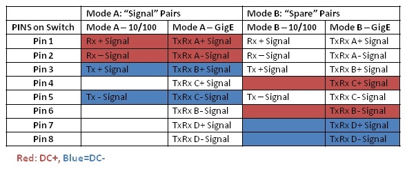
The 802.3af defines two modes of supplying power. Modes simply designate which wires carry the power and were created to accommodate different wiring schemes. Mode A provides power on the Signaling Pairs of Wires. Mode B provides power on the ‘Spare’ Pairs of wires. The terms ‘Spare’ and ‘Signaling’ can get very misleading in Gigabit Ethernet since all pairs are used for signaling. ‘Spare’ pairs refer to the wire pairs that WOULD be spare if the port was only running at 10/100 speeds.
I’ve included a pin-out table below for reference as well as a diagram of the TIA-568A & 568B wiring schemes, so that you can see which color wire corresponds to which pins. (Note: 568A/B standards have no relation to PoE Mode A/B: EIA/TIA 568 is a wiring scheme, and Mode A/B is a pin assignment for power.)


Notice that in both cases, power is only supplied on one set of pairs or the other. 802.3af does not allow power to exist on BOTH sets of pairs at the same time. The PoE network port (not the IP Phone or endpoint) decides which sets of wires will supply power.
PoE Gets Some Class
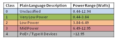
 Given the huge range of devices that might request network power, the 802.1af committee decided to put devices into categories, depending on how much power is required. For example, a tiny 1-line phone with no display requires far less power than an access point containing multiple radio transmitters and receivers.
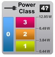
PoE Phones and other endpoints can signal to the PoE network what class of device it belongs to and how much power it may need. Class 0 devices are the mavericks of the world, refusing to categorize themselves. These rare devices might draw any power level from none to maximum — the only thing that we know for certain is that they are a PoE device. The other standard classes, 1-3, range from very low power, to low power, to mid-level power consumption. A class 4 device is a newer class of device requiring PoE+ (802.3at) and needs to draw more than the 12.95 Watt maximum provided by the original standard PoE. Class 4 devices must be powered by PoE+ ports and may not function correctly on a 802.3af PoE port.

Scary Old Equipment…
In case any of you are still running equipment that dates from 1999 through 2002 (you know who you are!): Many of Cisco’s early pre-standard PoE switches used signaling schemes involving Ethernet pulses and CDP protocol to request power. Most of these switches only provided up to 10 Watts per port, defaulting at 6.3 Watts. This older scheme was not upgradeable to the IEEE 802.3af standard which required hardware changes. If you have an ancient Cisco phone that won’t power up on PoE or if you have an ancient Cisco PoE switch that won’t power up “standard” PoE equipment, it may be time for an upgrade.
Hey Y’All – Watch This!
We’ll save PoE+ (802.3at) and the future of PoE for part 2 of this article, but we want to leave you with some practical thoughts and questions to ponder before we go. What power ‘things’ do we need to watch on our network?
- Do you know how many pre-standard, PoE, and PoE+ ports are available in your network?
- How many devices do you have in each category, and where are they?
- What new devices (or additional devices) are arriving in your building, and do you have spare PoE ports available for them?
- Do you know how much power your PoE equipment is drawing?
- When is the last time you’ve checked to see how many minutes of UPS backup you can provide if the power goes out? You can’t call for help (or to order a new UPS) if your phone is out!
- Some chassis-based switches require more (or upgraded) power supplies, especially when there are many PoE devices on the network — do you know how loaded your power supplies are?
- Is your company working green energy initiatives and looking to monitor and manage power consumption?
- PoE usage can increase heat generated by PoE switches — do you have adequate air-conditioning in place for your growth? (Or do you intend to wear shorts and Hawaiian shirts to work when you need to work in your equipment room?)
Go to: Part II, PoE Means More Power to You
- PoE+
- The Future of PoE
- When Things Go Wrong
- What PathSolutions is doing with PoE Management
See also: Our PoE checklist before investing in a PoE Solution.


